Measuring Mode <Object Detection>
How it Works
The measuring tool checks the substrate of the sensor area. Objects that are different from the material of the wall are detected.
If multiple objects are located over each other in the wall, the display will indicate the object whose surface is nearest to the measuring tool.
Detectable objects
- Plastic pipes (e.g. water-filled plastic pipes, such as underfloor or wall heating pipes, etc. with a diameter of at least 10 mm, or empty pipes with a diameter of at least 20 mm in solid surrounding material)
- Electrical cables (regardless of whether live or not)
- Three-phase power cables (e.g. to oven)
- Low-voltage cables (e.g. doorbell, telephone, network, smart home)
- All types of metal pipe, rod or carrier (e.g. steel, copper, aluminium)
- Reinforcing steel
- Wooden beams
- Cavities
Special measuring cases
Unfavourable conditions fundamentally impair the measuring result:
- Multi-layered walls
- Empty plastic pipes and wooden beams in cavities and lightweight partition walls
- Objects lying at an angle in the wall
- Metal surfaces and moist areas; if in a wall, these may be displayed as objects under certain conditions (e.g. high moisture content).
Please note that concrete requires several months to dry out completely. - Cavities in a wall; these may be displayed as objects
- Proximity to devices that generate strong magnetic or electromagnetic fields, e.g. mobile phone base stations or generators
- Before drilling, sawing or routing into walls, refer to other sources of information to ensure that you eliminate hazards. Since the measuring results can be influenced by ambient conditions or the wall material, there may be a hazard even though the indicator does not indicate an object within the sensor range.
Change the wall type
Always set the appropriate wall type for best possible measuring results. To do this, repeatedly press the left-hand (14) or right-hand arrow button (7) until the required wall type is displayed. Press the red start button (16) to accept the selection.
The maximum measuring depth is 8 cm. Any deviations from this value are described in the individual wall types and views.
Wall Type <Brick / Universal>
The <Brick / Universal> wall type is suitable for most applications in solid masonry or other homogeneous materials. It displays plastic pipes and metal objects as well as electrical and other cables. Cavities in masonry or empty plastic pipes with a diameter of less than 2 cm may not be displayed.
Wall Type <Concrete>
The <Concrete> wall type is suitable for applications in dry concrete. It displays plastic pipes and metal objects as well as electrical and other cables. Empty plastic pipes with a diameter of less than 2 cm may not be displayed.
When selecting the wall type, you can additionally set the maximum measuring depth between 8 cm and 20 cm.
Wall Type <Drywall>
The <Drywall> wall type is suitable for detecting timber joists and metal supports, as well as electrical and other cables in drywalls (wood, plasterboard, etc.). Filled plastic pipes and wooden beams appear identical on the display. Empty plastic pipes are not recognised.
Wall Type <Panel Heating>
The <Panel Heating> wall type is especially suitable for detecting metal, metal-composite and water-filled plastic pipes and electrical cables. Empty plastic pipes are not displayed.
Wall Type <Vertical Coring Brick>
The <Vertical Coring Brick> wall type is especially suitable for applications in vertically perforated bricks. Vertically perforated bricks are bricks with many small, mostly vertical, cavities. It displays metal objects, electrical and other cables, as well as water-filled plastic pipes. Cavities or empty plastic pipes may not be displayed.
Wall Type <Horizontal Coring Brick>
The <Horizontal Coring Brick> wall type is especially suitable for applications in horizontally perforated bricks. Horizontally perforated bricks are bricks with a few, mostly horizontal, cavities. It displays flat lying metal objects, electrical and other cables, as well as water-filled plastic pipes up to a maximum measuring depth of 5 cm. Cavities or empty plastic pipes may not be displayed.
Wall Type <Early Age Concrete>
The <Early Age Concrete> wall type is especially suitable for applications in concrete which has not yet fully cured and dried. Metal objects are displayed up to a maximum measuring depth of 6 cm. Plastic pipes and cables may not be displayed. A distinction between live and voltage-free conductors is not possible.
Please observe that concrete requires several months to cure and dry completely.
Change the view
To change the view, repeatedly press the top (17) or bottom select button (12) until the required view is displayed. Press the red start button (16) to accept the selection.
<Spot View>
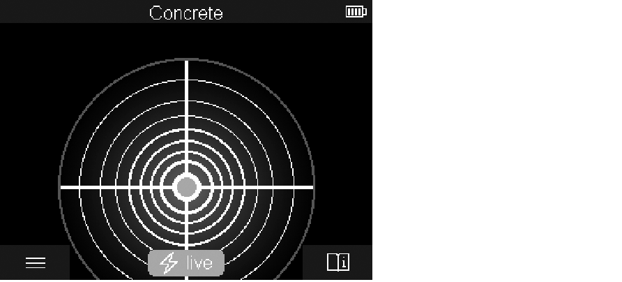
In the <Spot View>, a first measuring result is already displayed without moving the measuring tool over the substrate. It is therefore particularly suitable for measurements in corners or narrow places. The maximum measuring depth is 6 cm. Objects found are displayed with material properties, if available, but without depth information.
Whenever possible, you should also move the measuring tool over the substrate in the <Spot View> to ensure the best possible measurements. Locating plastic pipes and timber joints is particularly limited without moving the measuring tool.
Measuring indicator:
If no object is found, only the outer circle will appear on the display and it will light up green.
If there is an object nearby, the outer circle will light up red. The closer the measuring tool is to an object, the more the deflection in the measuring indicator (number of circles) will increase. The deflection decreases when the measuring tool moves away from the object.
Orientation arrows are displayed if the signal strength is sufficient. To specifically locate the object's centre, move the measuring tool in the direction of the orientation arrows. Above the centre of an object, the measuring indicator will exhibit maximum deflection, and with sufficient signal strength, a centre cross is displayed. The colour coding for the material property is identical to that in the <Object View>.
If the orientation arrows or the centre cross are not displayed, an object may nevertheless be located in the immediate vicinity.
<Object View>
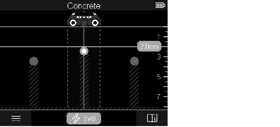
The <Object View> offers the best possible measuring results and the maximum measuring depths. The detected objects are displayed over the measuring path with depth information and, if available, with material properties.
Measuring process:
- Place the measuring tool on the substrate and move it over the substrate in the direction of travel. The measuring results are shown on the display after a minimum measuring path of approx. 10 cm.
- Always move the measuring tool in a straight line while applying light pressure over the substrate so that the wheels remain in contact with the wall.
- To obtain optimum measuring results, move the measuring tool slowly over the entire area to be checked and observe the measuring results as you move the tool back. The measuring path should be at least 40 cm.
- You can start a new measurement at any time by pressing the red start button (16).
- If you lift the measuring tool away from the wall during the measuring process, the last measuring result obtained remains on the display. The measurement is restarted when the device is set down or moved.
The tool's function allows for reliable detection of the nearest edges of objects that run transverse to the direction of movement of the measuring tool (see figure C). For this reason, always move crosswise over the area to be checked.
To locate objects, moving the measuring tool once over the measuring path is sufficient. To identify the exact location of a detected object and to mark the object, move the measuring tool back over the measuring path.
The direction of a found object in a wall can be determined by moving along several offset measuring paths one after another.
Measuring indicator:
If no object was detected in the sensor range, the dashed lines and the centre line are completely green.
If an object was detected under the sensor, it will appear in the sensor range between the two dashed lines of the display. The two dashed lines and the centre line are at least partially red.
In the right-hand depth scale, the object depth to the nearest edge of the found object is displayed.
The representation of the properties of detected objects in the display can deviate from the actual object properties. In particular, very thin objects appear thicker on the display. Larger, cylindrical objects (e.g. plastic pipes or water pipes) may appear narrower on the display than they actually are.
Depending on type and depth of the object, identification of the material is possible. The type of material can be recognised by the colour of the object in the display:
|
Yellow: |
Live object |
Blue: | Magnetic metal (e.g. reinforcing steel) |
Turquoise: | Non-magnetic metal (e.g. copper pipe) |
White: | Non-metal material (e.g. wood, plastic) |
Grey: | Material property unknown |
Information on material identification:
- For live objects, no further characteristic is displayed.
- Three-phase mains wiring may not be detected as live conductors.
- At a relative humidity above 50 %, detecting the "live" property may be limited.
Marking objects:
- If you want to mark a found object on the substrate, move the measuring tool so that the object is centred on the centre line in the display. Use the upper marking aid (1) as well as the left-hand and right-hand marking aid (5) to make a mark on the substrate. The centre of the object is located at the intersection point of the drawn markers.
- Alternatively, move the measuring tool to the left or right until the found object is centered on one of the two dashed lines in the display. Then it is located under the corresponding outer edge of the measuring tool. Draw a line along this outer edge on the substrate and mark the position of the corresponding lateral marking aid (5) on this line. This is the centre of the object.
- The direction of a found object in a wall can be marked by moving along several offset measuring paths one after another and connecting the respective markings.
<Signal View 2D>
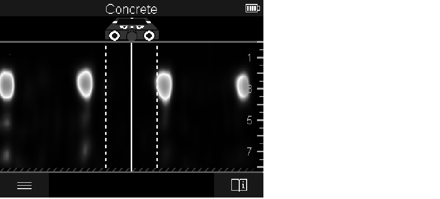
The <Signal View 2D> indicates the signal strength at each measuring point in combination with the object depth. The <Signal View 2D> is a variant of the <Object View>. It displays signal strengths instead of object symbols. The maximum signal strength represents the upper edge of the objects.
The <Signal View 2D> can be used to locate closely adjacent objects and to better assess complicated material structures. Weaker objects and objects in a row can also be found under certain circumstances.
Follow the instructions on the measuring process in <Object View>.
<Signal View>
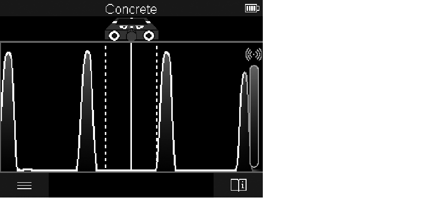
The <Signal View> displays the signal strength at each measuring point without information on the object depth.
The <Signal View> can be used to locate closely adjacent objects and to better assess complicated material structures based on the signal path.
Follow the instructions on the measuring process in <Object View>.